Reverse engineering Janome embroidery cards
I recently bought a Janome Memory Craft 8000 from eBay for a sewing project. The machine dates from the early 90s, but was top-of-the-range when it was released. It was also (one of?) the first machines to embroider designs off a memory card. I’ve used it for sewing quite successfully, but have ended up going down a rabbit hole with its embroidery features….
The vendor was also selling a “Scan n Sew” unit. This is a standalone device that consists of a monochrome hand scanner integrated with a roughly laptop sized box. The device allows you to scan a design and automatically convert it to an embroidery file, which is written to a special memory card.
I’ve been trying to figure out the format of the data on the memory cards, with a view to writing my own designs to a custom card (TLDR - I’ve not got that far).
The pyembroidery library, which is used by InkStitch can read the .sew files which (I thought) my machine used, and write .jef files (which is the format used by newer Janome machines, which has some similarities with .sew files).
I found an (abandoned?) attempt at reading the cards of the newer 9000 model on hackaday (these cards are 512kb capacity, mine are 128kb; I don’t know whether the format of the designs is different, or if they’re just larger capacity).
Other tools
There were 3rd party devices to allow users to write their own designs to a custom card. I’ve been able to find out very little about these; they date from around the turn of the century (that makes me feel old), and there’s little information about them online:
- Amazing Box II from Amazing Designs (user manual) (archive.org links)
- Echidna Easy Writer (archive.org link) (found via https://sewing.patternreview.com/SewingDiscussions/topic/4921)
- PES2Card
- Multi converter
AFAICT they all use a custom box connected by serial or USB to the PC, and use proprietary software to send designs to the card. They occasionally pop up on eBay, but usually for sale in the US.
Janome made a similar box for the MC 9000 (the successor to the MC 8000) called the Customizer 2000. The Scan’n’Sew seems to be the only official way of creating your own designs for the MC 8000 though.
I’ve split this write-up into 4 sections; getting the data off the cards, decoding the design format used on the cards, writing data and making a new rewritable card.
Getting data off the cards
Physical format
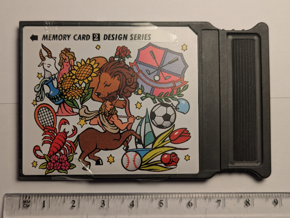
The machine came with a single (read only card), which contains the alphabet in various fonts for embroidering words. When new the machine would’ve come with an additional card containing designs, but I didn’t get this. Various cards come up for sale on eBay containing different designs. I’ve bought a few of these, including the design card that would’ve come with the machine.
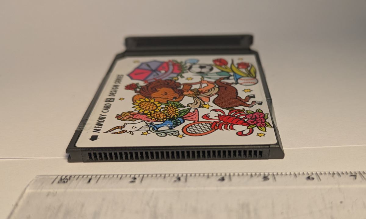
The cards look like PCMCIA cards, except they have only a single row of 34 connectors, vs 2x34 on a PCMCIA card. The Scan n Sew card has the same form factor, but also contains a button cell battery to maintain the memory. This card has (according to the label) a 32 kb rom and 96 kb ram(!). The Scan n Sew allows you to store 4 designs, each of up to 4 colours. This contrasts with the ROM cards, which have more designs and more colours per design.
Some searching for 34 pin memory eventually led me to the retrocomputing forum where someone provided a potential pin-out for a similar looking card, albeit with a lower capacity.
The Scan N Sew contains a D70320GJ-8 microcontroller. Checking the continuity from its address and data lines to the connector in the scan n sew confirmed the pin assignments were correct, and gave me the pins for the A15 and A16 lines (A17 was also connected on the scan n sew, but isn’t used - perhaps a larger capacity card was planned)
Connector pinout
(Pin 1 is closest to the top of the card when inserted in the machine. With the PCB chip side up, and the connector on the right, this is the north of the PCB)
- 5V
- A14
- A12
- EC?? (Not connected on ROM card)
- A7
- A13
- NC
- NC
- A6
- A8
- A5
- A9
- A4
- A11
- A3
- OE(?) (Not connected on ROM card)
- A2
- A10
- A1
- ?CS?? (Connected to +5v via 20K resistor)
- A17 (Not connected on ROM card)
- A15
- A16
- A0
- D7
- D0
- D6
- D1
- D5
- D2
- D4
- D3
- GND
- GND
Extracting the data
I planned to try and read the data off the card by wiring up an old PCMCIA connector (lightly modified with a hacksaw). Looking at the connector on the machine, it looks like the pins are offset from the centre, so I was hoping that this would work. After much soldering I concluded that the pins weren’t making contact, so gave up on that approach. (With hindsight I should’ve just soldered the two ground pins and checked for continuity between them via the card)
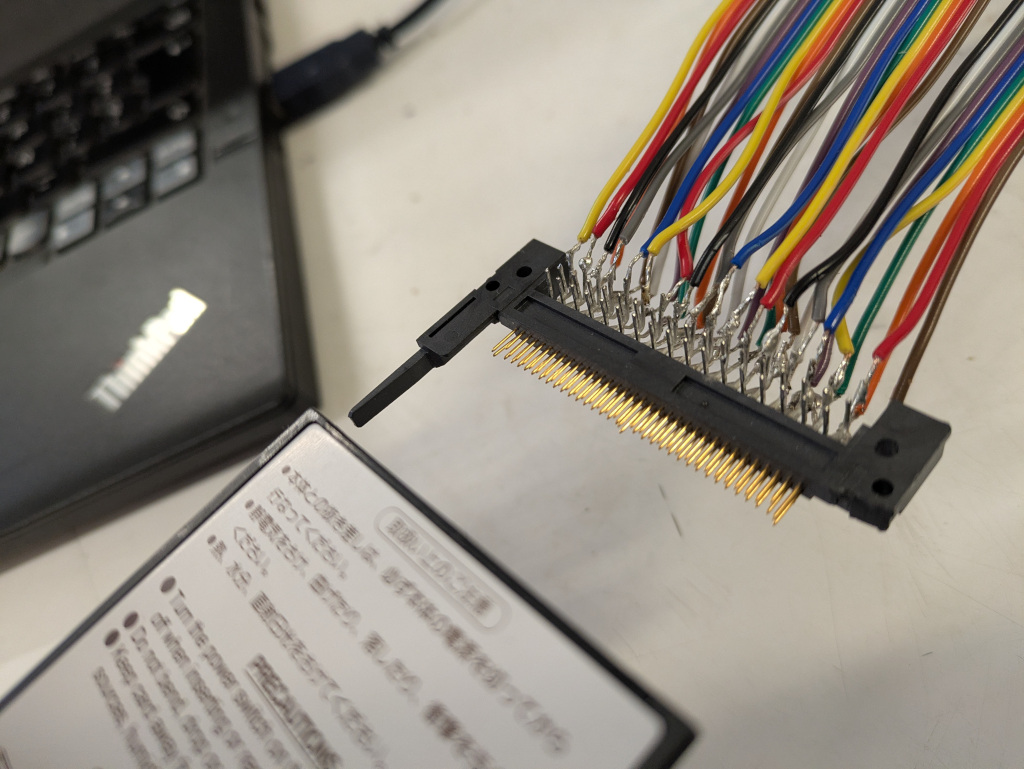
I then decided to solder directly to the back of the connector on a dismantled card. I should’ve used thinner wire :-(

Reading the data
A link on the PES2Card site helpfully listed the chip numbers in each of the after market cards. These are all 29F040B. Searching for this led me to a post on the Arduino forum, to make a programmable cartridge for a gameboy.
Using some of the code from this thread, and the repo for the OP’s code, I built a circuit using a couple of shift 8 bit shift registers (plus an additional GPIO line for A16) to read the data from the card.
This was getting something off the card, but the start of the card appeared to be blank (this turned out to be correct), and I eventually realised some areas were repeated. This led me to suspect a short on a couple of the address lines.
I then learned that these exist. This simplified things greatly(!)
Wiring up the Arduino with the clip, I was able to figure out the pinout for the ROM, and get a dump of it.
Chip pinout
| pin | pin |
|---|---|
| 1. A15 | 28. +5v |
| 2. A12 | 27. A14 |
| 3. A7 | 26. A13 |
| 4. A6 | 25. A8 |
| 5. A5 | 24. A9 |
| 6. A4 | 23. A11 |
| 7. A3 | 22. A16 |
| 8. A2 | 21. A10 |
| 9. A1 | 20. CS(?) |
| 10. A0 | 19. D7 |
| 11. D0 | 18. D6 |
| 12. D1 | 17. D5 |
| 13. D2 | 16. D4 |
| 14. GND | 15. D3 |
Decoding the ROM
The research I’d done suggested that early Janome machines use the SEW file format, which was succeeded by their JEF format. The pyembroidery library has a reader for both of these file types. I could find out little beyond that about the format, beyond the source code for pyembroidery’s reader until I found a page for an (abandoned?) KDE embroidery project which had some information on the specification of both file types.
I was expecting to find chunks of memory each containing a sew file, and some sort of FAT to point the machine to the start address of each design. Sadly this proved not to be the case.
The first 0x2000 of all the cards I read is blank. I tried reading the dump in as a sew file using pyembroidery. Trying a few promising looking offsets gave me something that looked like a part of a design.
This means we know the stitch data is stored in the same format as the sew files (2s complement. 1 byte for x, 1 byte for y, 2 byte control characters, for, e.g. move.) I worked out that we need to start on an even byte otherwise design goes wrong on a control character.
I then looked at what we got if we treat everything as a stitch in the entire dump, to try and figure out how the data are arranged. This is shown below. (this doesn’t display properly on mobile)
The stitch data is quite hard to see amongst all the other stuff on the card. It’s highlighted in red on the (zoomable) plot above. One lot of stitch data is in the bottom 64k of the chip, the other in the upper.
There’s a separate set of stitches for each colour in each design, but no obvious delimiter between designs and colours (the stuff between designs corresponds to move commands to move the needle to the right place to start the next colour. As the biggest move is 12.7mm multiple moves are sometimes needed to get to the right place).
An Easter egg
I noticed what I thought was an Easter egg in the data, at the end of the first bank of stitches:
Unfortunately looking at the other bank of stitches, and data on other cards showed that there was often “junk” at the end of the stitch data (and elsewhere on the cards). Presumably whatever method was used to make the cards didn’t wipe the image used by the previous card, leading to these “ghosts”
Finding a FAT
I located the start address of each colour per pattern (“chunk”), and looked for these addresses elsewhere on the card. I located these addresses at 0xFA00 (and 0x1FA00), stored little endian. The addresses in the upper memory bank just use 0x10000 as a mask. There were also some “dummy” values in this area, that didn’t correspond to a memory address. I identified more likely addresses at 0XFC00 (and 0x1FC00). These appear correspond to the end address of each chunk of stitches
I read these in pairwise (i.e. 0xFA00 and 0xFC00, 0xFA02 and 0xFC02), and kept the chunk if both start and end addresses are plausible (e.g. different, neither is FF FF etc). This isn’t perfect; there a few false positives, but it mostly works to identify the chunks of stitches referred to on the card (and removes the Easter eggs/ghost chunks)
These can be read as a pattern using a lightly modified version of the SEW reader in Pyembroidery, which allows them to be saved as an svg (or any of the other embroidery formats pyembroidery supports).
This doesn’t, however, allow us to distinguish between the patterns on a card, or to establish what colour is associated with each chunk.

Or, by working out which chunk belongs to each pattern, just extract a single pattern:

The other stuff on the card
Bitmaps
The sew file format, which I’d naively assumed the machine used, contains bitmaps of the pattern in various resolutions (presumably for the machine to display as a preview). I looked for bitmaps on other parts of the card to see whether these existed elsewhere on the card.
There are bitmaps containing the overall design and previews for each colour on the card (and the names of the colours as bitmaps). The former are 4 bytes wide (1 bit/pixel), the latter are 3 bytes wide:
There are also images for the touch-screen’s icons:
And some text in Japanese:
I assume this is ghost data from a different card (translating it in Google Translate suggests it’s instructions for an applique, where you cut out the design and stick it on another piece of fabric)
The offsets for the various image types vary by card, but seem to be in similar places.
Device firmware?
I compared the rom dumps of several of the cards in a hex editor. All have the following features:
- Nothing until 0x2000
- Some sort of lookup just after this:
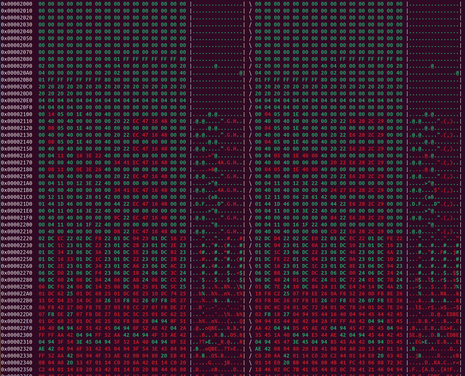
Given the touchscreen button bitmaps are included on the ROM, I’m assuming some of the remaining data is firmware to drive the machine.
I’ve not got much further than this. 0x12978 seems to have the number of colours in each design.
Writing data
I’m fairly happy I could modify the gameboy write code to write an image to a suitable chip, such as the 29F010B.
I’ve successfully found the start and end addresses of each chunk, it should be possible to overwrite bits of an existing ROM image with the new stitches, and update the addresses to the new regions (and optionally update the icon bitmaps for the design). The new design would need to have the same or fewer colours than the design being overwritten, as I’ve not yet figured out how to link each chunk to a design. In principle, this should allow custom designs to be written, using a modified version of PyEmbroidery’s JEF writer functionality (the part containing the stitches is basically the same).
I’ve held off trying to get any further than this until I find a way of making a homebrew card.
Making a new card
I’m really not sure how to start with this :-( The card connector obsolete. I’m not sure whether it was ever used on anything besides these machines. This was presumably also an issue for the people behind the Echidna converter: “you need to supply us an exchange memory card to suit the Memory Craft 8000. This card can be any MC8000 card that you already own.For example you may have a card that you don™t like or are never likely to use.”
It might be possible to modify a PCMCIA card (PCMCIA to CF adaptor? But those are a little thicker). The pins on the machine should be longer, given the ones on the PCMCIA socket were too short. I’ve not tried this yet, as I’m reluctant to risk damaging the connector inside the machine. It’s very fiddly to solder the 0.05” connectors.
One approach might be to sacrifice an existing card and connect wires from its connector to a breadboard containing a flash chip. This could be programmed via a clip.
Update 9 April 2025
I found some connectors on AliExpress that I thought might work, having the correct spacing (1.27mm).
I made a FreeCAD model of the card, which I 3d printed. I cut the connector down to 34 pins and glued it into the card. Unfortunately this couldn’t be inserted into the machine’s socket. I suspect the pins in the machine are wider than the connectors’ holes.
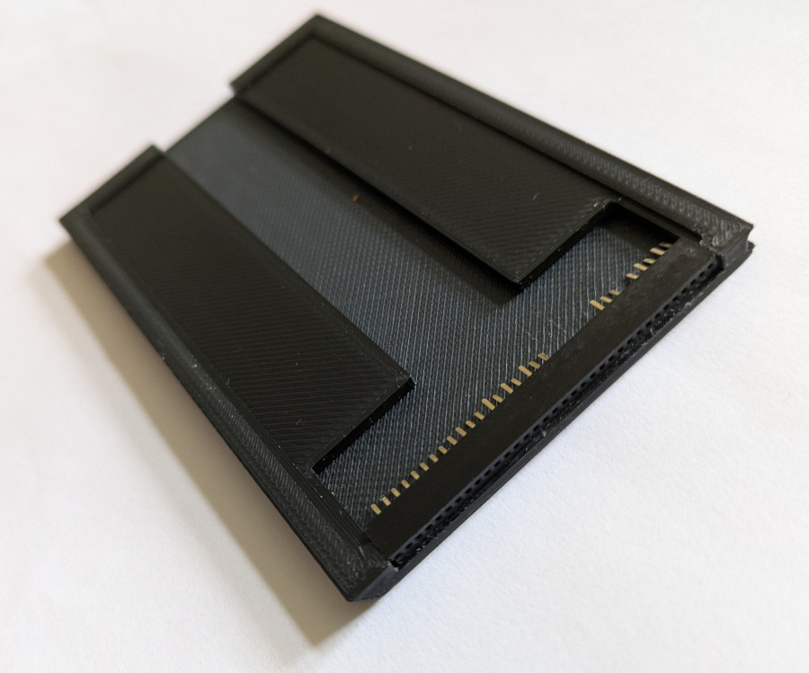 I’ve been unable to find a connector that more closely matches the original.
Feel free to get in touch if you’ve any suggestions.
Update: Further progress is here
Code
The sketch to read a ROM is at https://github.com/mawds/read_mc8000_rom/
The code I developed to look at the ROM, building on pyembroidery is in the mc8000 branch of my fork of their repository: https://github.com/mawds/pyembroidery/tree/mc8000 This defines a JanomeCard class which allows you to read the stitch offsets from a card dump, output (selected) chunks, etc. It’s very much a work in progress.
Acknowlegements
Thanks to Roger for the encouragement!